

Our Fields of Activity:
1- Design and Implementation of control system and distribution substation protection
2- Design and production of LV and MV panels
3- Engineering and after sales services of SIEMENS relays
4- commissioning of distribution substations in Cement and steel industry
5- commissioning of protection systems in power plants
6- Design and implementation of Industrial automation projects
7- Design and implementation of boiler control projects in power plants, refineries and industries
8- Design and implementation of cement and steel factories in partnership with ELAKS company (Ukraine based )
9- Design and implementation of BMS (Building Automation System)
10- Design and implementation of Remote Controlling projects
11- Design and production of Power and control Panels
12- Engineering and operating Energy Management Projects in accordance with ISO50001
Designing LV and MV distribution substations
In this section we provide designing process of protection systems and power distribution panels in the range of 6 kV – 33 kV based on the demanded protection and corresponding relays.
As the designing process completes, production of the argued panels start in the factory and after that testing process begins to ensure the integrity and reliability of the whole product.
Engineering and after sales services of Relays
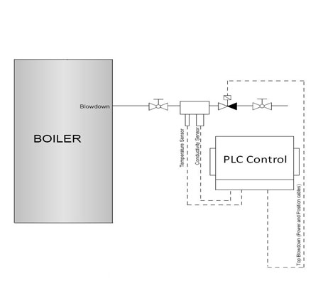
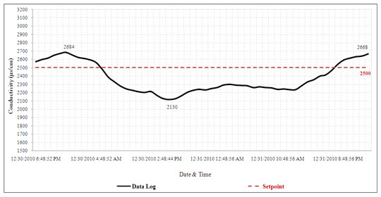
Fig.6 shows the Conductivity rate over time with manual blow down and Fig.7 shows the Conductivity rate over time with automated TDS control system. These charts are based on data from one Iran’s oil refinery. It is obvious that the automated control system has better performance.
Fig.6Conductivity rate over time with manual blow down
In this section, appropriate relays are selected regarding the customer demands as well as providing them with technical consults. After acknowledgment of approval on the initial design, we deliver the desired products to the customer and the testing services would be provided to the customer if needed.
Commissioning of power plants protection
As all the relay systems of Trans and generators in power plants and power transmission substations need annual testing and tuning, we provide total services regarding annual test and tuning protection relays.
Resume on technical services and commissioning protection relays
13- Maragheh Paper Factory
14- Micom ALSTOM, ABB Relays
15- Transformer protection relays (10 Devices)
16- Motor protection relays (150 Devices)
17- Line protection relays (4 Devices)
18- Karoon1 1000 MW hydro power plant (ShahidAbbaspour) including four 250 MW Units
19- GEC ALSTOM Relays
20- Generator protection relays (16 Devices)
21- Transformer protection relays (12 Devices)
22- Line protection relays (4 Devices)
23- 24 KV panels of distribution substations in Syria (400 Devices)
24- ALSTOM – Micom series Relays
25- Output feeder protection relays (350 Devices)
26- Transformer protection relays (40 devices)
27- BUS protection relays (10 devices)
28- 33 KV panels of distribution SARCHAHI substation
29- ABB Relays
30- Output feeder protection relays (30 Devices)
31- Transformer protection relays (10 devices)
32- Distance Line protection relays (2 devices)
33- 20 KV panels of ZANJAN regional power bureau
34- ABB Relays
35- Output feeder protection relays (15 Devices)
36- Transformer protection relays (5 devices)
Engineering and Procurement of Boiler Control system
Given the importance of boiler control system in every industry, a specific section of the Payesh Energy Company focuseson boiler control system. Our activities in this area includes:
1-Desgine and engineering control system
2- Procurement of instruments
3-Construction of Control cabinet
4-programming PLC according to control logic and design HMI pages in monitoring software.
Increase the Efficiency and Combustion of Steam Boilers
Our company is benefiting from valuable experiences running several projects and Installing PLC systems on boilers of Mashhad and Shiraz refineries and Mashhad power plant (pilot project supported by the Iranian fuel conservation company – a subsidiary of National Iranian Oil Company)
We also gained positive results on energy consumption optimization in those projects by changing the philosophy of combustion control systems and blow down and adding a combustion analyzer to plants.
Payesh Energy Co. declares its full readiness to design, providing instrumentationand installation, commissioning and training for automatic digital control systems.
Installing the system in the Mashhad boiler plant (260 tones per hour) and Shiraz refinery boiler (40 tons per hour) leads to increased efficiency of 4.0 and 63.1 percent and it obtains the annual savings equivalent to 8 and 3.2 million Cubic meters of natural gas .
The installation of automatic control system of blow down in Shiraz Refinery has brought 22% reduction of blow down.
The benefits of this project include:
– An increase in boiler efficiency and a significant reduction in fuel consumption and water use
– Maintain the highest boiler efficiency under all operating conditions and climates
– Reduction of current costs, especially in the older parts of pneumatic systems
– An increase in boiler efficiency and confidence and consolidation in pressure steam for use in downstream units
-Ease of operation and improve the quality of system control byOperator
– Monitoring conditions, and the ability to fully data registration also online computation and optimization of efficiency
– Improving the quality of work and reducing equipment depreciation
In The procedures of project running with EPC-f method, implementation costs are paid by the company and after testing performance of the project over a period, Investment amount, will be paid by the employer.
Obviously, this method guarantees the performance, with no investment for refinery complex on the action taken and repay debts resulting from savings made in fuel supply
In this section, a brief description of effective mechanisms to control the boiler is provided.
– Introduction of control systems and control systems to optimize combustion boiler and blow down
Introduction
Steam boilers are one of the most important energy carriers, usually are one of the important components, and are major energy consumers. Regardless of the boiler structure, the most important parameter in terms of energy consumption equipment is the thermal energy efficiency.
The definition of this efficiency is the ratio of energy received by steam to the Energy given by fuel.
The most important loss of energy in boilers are, energy wasted through the chimney, heat loss from the body and heat loss through blow down at high temperature.
Heat loss through the chimney consists of several parts, such as heat loss due to high temperature combustion gases, waste heat from the water in the combustion gases, unburned hydrocarbon, carbon monoxide and the presence of soot.
It is seen that the rate of air supplied to the combustion to the rate of fuel affect all these parameters and with the appropriate Adjusting the high heat losses can be avoided.
Also, due to the high temperature of blow down that is used to adjust the amount of total dissolved solids in water and prevent the formation of deposits and other problems, a large amount of energy is wasted. Since the amount of blow down usually determined on the basis of experience, so having a proper standard of the measurements with suitable equipment, we can fine-tune the amount of blow down, this way the loss of energy is prevented.
The variety of boiler combustion control systems
It is clear that to fully burn fuel with specific composition, In perfect condition (stoichiometric) a fixed amount of oxygen in the air will be required, but because of difference in actual conditions with the theory and the inability of burner to perform complete combustion, should be a greater amount of air supplied to the combustion to occur completely. The proper amount depends on quality of burners, fuel and air-fuel mixture. On the other hand, it is clear that increasing the amount of air, which is entered with ambient temperature and extracted with chimney temperature, increases heat loss. Thus we see that on one hand reducing the combustion air leads to soot, unburned hydrocarbonsand carbon monoxide in general Will cause incomplete combustion, on the other hand increasing it will cause combustion air thermal dissipation. The control of combustion air is one of the most important factors in maintaining good working conditions and improve the efficiency of the boiler.
The boiler control can be done manually or automatically.
Manual control is tiresome and requires constant care of tools to establish safe conditions. Also In order to alert users to perform corrective measures, one must install warning devices. Todays The use of automatic and semi-automatic control systems, in many of the important equipment and devices are common and in many cases the use of manual control cannot be imagined .
Boiler controls used to regulate the flow rate, temperature and pressure and is done to protect the boiler from possible risks. Regardless of the boiler protection systems such as pressure and temperature, protection prevents injuries and accidents in different parts of it, the most important part of boiler control is combustion control. In fact, with combustion control, we can supply true rate of combustion and heat load requirements and at the same time control the right amount of the combustion air, which will be followed by improvement in boiler efficiency.
Boiler automatic control systems due to the equipment used and the complexity of their management philosophy,are divided into three main categories that include: power on / off systems, mechanical regulating and control systems for measuring.
the following section measurement and control system set up as a modern control system that is used in the projects carried out by the company are been investigated.
– Measurement and regulation systems
In this system the valve of fueland air damper are controlled withtheir respective commands. Signal of the pressure of steam supply line used to control the pressure. Commands are sent from this controller to the other 2 controllers of flow with the duty of the control fuel valve and air damper. In a full system of this type, fuel and intake air flows are measured and used as feedback in the respective controller for each boiler. Each of these controls independently dischargeit self’s valve or damper to regulate so that correct rate or set point obtained.in this manner The good combustion conditions, regardless of changes in system robustness or features of the controller is obtained, is provided. The control system is a closed loop system. Depending on the different ways of using this type of controller and use or non-use of the fuel and air flow, these controllers are divided to parallel regulatory systems and Parallel and series regulatory measures. In Figure 1, the full sample diagram of the control and regulation of parallel measurements using both O2 and CO sensors are shown
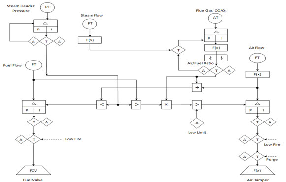
Figure 1. Flowchart plan of parallel measurement control and regulation
According to Figure 1, this control system for measuring and adjusting isconsists of 4 parts
These are:
the control of the burner modular steam according to pressure management (Firing Demand), control of carbon monoxide withanalysis of combustion gases (CO Measuring Control) to set the amount of excess air in a safe margin, controlling oxygen based on combustion gas analysis (O2 Measuring Control)for softcontrol and regulation of the boiler extra air for optimum efficiency and ultimately the air-fuel cross limiting control system to ensure safe air-fuel ratio. The control units individually marked in Figure 3.
Measurement and control systems can adjust all useful capabilities such as regulatory excess air, oxygen regulators, block the production of carbon monoxide and cross limiting of air and fuel. The concurrency control parameter in the control systems is one of the most important characteristics to prevent the rich fuelin the boiler.
Combustion control consists of two temperature control and control of fuel to air ratio of the combustion chamber. The task of combustion control system is to continually provide enough air for, furnace fuel combustion without smoke and soot extract from the chimney and also forbid hazardous combustion air to fuel ratios, which can turn off the burner.
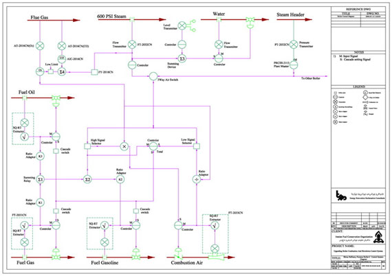
Figure 2. The measurement control and regulation systems designed in parallel with
Excess air control of a refinery boiler
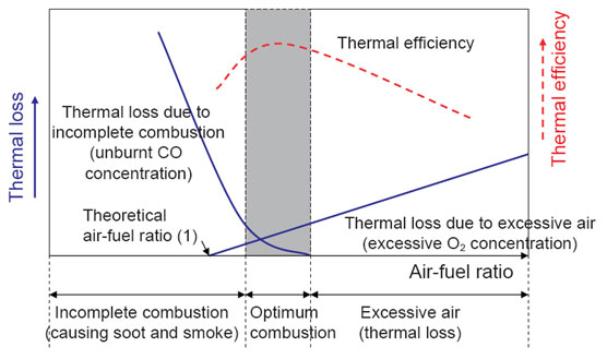
Figure 3. The range of variation of the excess air in order to achieve optimum thermal efficiency
Air-fuel delay control strategy
Delay strategy creates combustion control strategythat ensures it will never be dangerous air-fuel ratio in the system, this part of the system always increases the air flow before the increase in overload of boiler fuel flow and fuel flow to reduce air flow in the boiler. Figure 4 illustrates this well.
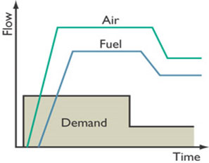
Figure 4. Cross-Limiting system performance to ensure the proper ratio of air to fuel
Oxygen regulation
Knowing the amount of oxygen in the chimney causes better control of the combustion. Adding a module due to better control the amount of oxygen and excess air. The system makes quick return to set point when it gets into any kind of disturbance. Another advantage of the reduced CO output of the control systems that have these strategies are.
Fig.7Conductivity rate over time with after installing automated TDS control system
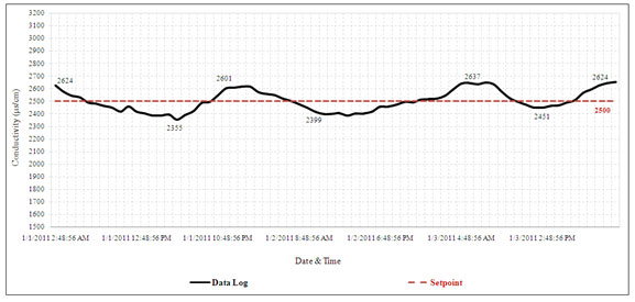
Fig.8Conductivity comparison between manualandautomaticblow downduring57hours ofboiler work
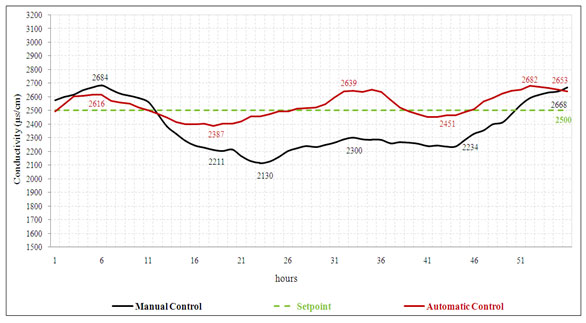
Figure 8 showsa comparison of Conductivity in bothmanual and automatic modesbased onoperatingresultsrecordedduring the57hours ofthe boiler working condition.Accordingtothisgraphwater loss andtheheating wasteis reduced.
Theimplementation ofboilerautomatic control system
Data collection
Due to thesensitivityof proper implementation ofindustrialautomation it is necessaryto collectdatain the field that is going to be automated. In thissectionall the information anddocuments such as tables,data sheets, drawings and instructionsshould be collectedtoexamine them in detail.
Study Information
After data collection, careful monitoring will begin in different parts. By the end of this section a proper view will be available to experts of the company.
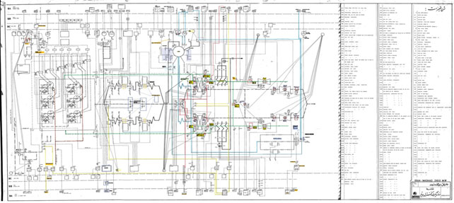
Fig.9P&ID plan of Power Plant Boiler
Evaluation ofexisting equipment,accordingtothe received documents
Along with reviewing documents identifying equipment and their process will becarefullystudied.
Dispatch of experts and visits the unit
By the end of the preliminaries, the Mabna’s expert team will be sent to the site to inspect, measure, line-up to ensure greater familiarity.
Evaluation workingsystems andcompare it withthe systemin the map
Formore accurateevaluation of the system, working systems will be compared to designed system.
Different measurements will be done in different working conditions. These measurements generally contain three measuring groups combustion parameters, electric measurements and instrumentation and physical measurements which results can show proper view from efficiency and operation.
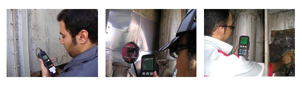
Figure10- sample measuring
Calculations, technical and equipment requirements of projects and provide P&ID and data sheets
Compare of information
Since collection of information from factory documents and visit systems, these information are compared with together and thus final values select to complete datasheets and P&ID.
Send information to notification and confirmation
Since extract precise information and conclusion of them and solve errors, the list of information send to technical and engineering unit to confirmation because these information is very important and wrong in them cause the project is damaged.
Provide equipment datasheets and plans in standard forms
According to international standards, new control plan and list of equipment datasheets provide to all equipment. Figure 12, 13
Finalizing plans and datasheets with confirmative information
Since review and finalizing information, list of them will confirm by client
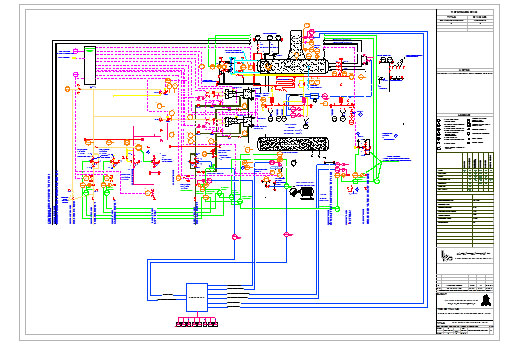
Figure11: P&ID to control refinery boiler
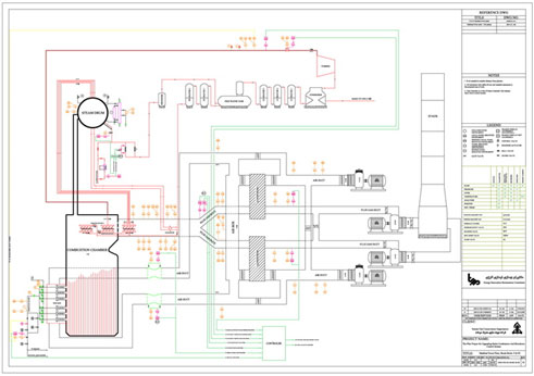
Figure12: P&ID to control powerhouse boiler
Vendor list confirmation and order equipment
Since check all required equipment and obtain confirmation of client, the equipment will order
Install equipmentSince delivery of all equipment, the installation phase will start which including installation of pipes, fittings, cables, manifolds.
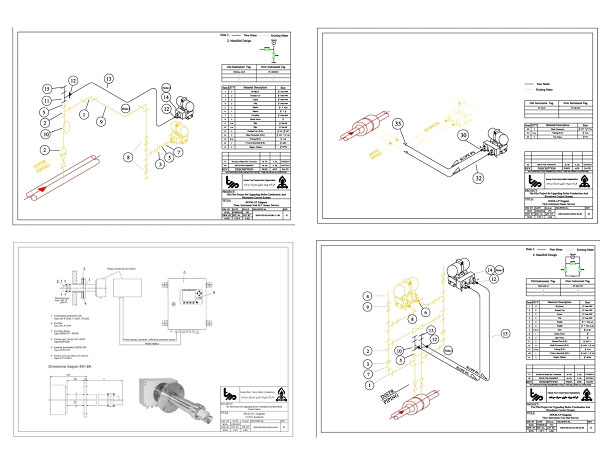
Figure13: samples of equipment installationa
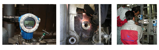
Figure14: pictures of installing instrumentation and combustion gases analyzerin boiler
Cabling
Cablingphase include installation of trellis, cable reels, cable tray in separated route, conduit and preparing cable tray in common route
Multi core cable
Between junction box and PLC panel use multi core shielded PVC cable
Single cable
Between junction box and equipment use single shielded PVC cable
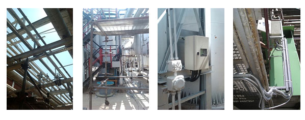
Figure 15: pictures of cabling in boiler
Junction box
Junction boxes are Rittal type and IP65. The using glands are anti-explosion and metal
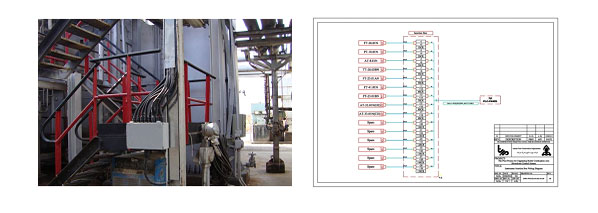
Figure 16: sample of junction box
Combustion gases analyzer
Combustion gases analyzer is a heart of system and high quality of it cause long term controlling and high operation of combustion system. Combustion gases analyzer installs output of combustion gases patch. Combustion gases analyzer include 2 parts, Probe and transmitter.
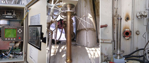
Figure17: installed analyzers in different boilers
Instrumentationequipment include flow, pressure and level transmitters which order according confirmation list of client. All of instrumentation equipment in this project have attached in attachment.

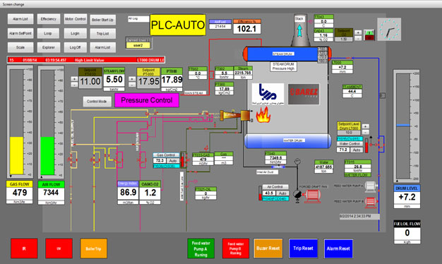
Control Panel of Boiler
Control system forboiler is PLC S7-300 from Siemens
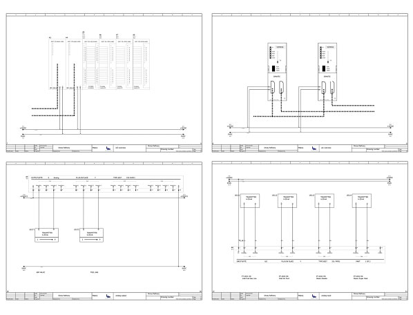
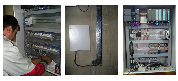
Figure20: PLC Control panels
Programming and Design ofHMI pages for Boiler
Programming of control logic for boiler and design HMI pictures for operation
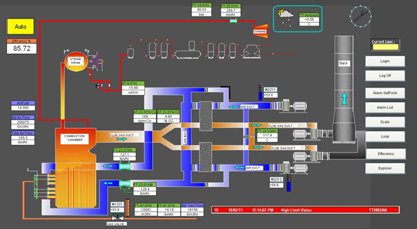
Figure17: Sample of Boiler HMI
Substation Automation by RTU560ABB132/20KV
This substation located in Sangerd far fromSabzevar city, this substation feeder’s agriculture wells.
We used from RTU560 ABB for remote control and monitoring.
In communication between this substation and Sabzevar city we used Fiber optic cables.
Protection relays and meters are Siprotect from Siemens.

HMI picture of Communication system
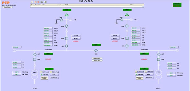
HMI picture of Substation Single line
This substation controlledfromSabzevar city, allcircuit breakers can be control from this system remotely.
All alarms and events can be observation in this HMI software.
Protection relays status and operation demonstrated in HMI.
Pars Animal food production Line Automation
This project is a animal food production line that we used from Bouhler company machines
we used from PLC S7-412Siemensfor control systems.
This control system consist ofPLC andFrequency driverand Level transmitters and speed monitors
In project have 2000 input/outputsignals consisting of analog and digital.
PLC control ofall production line include ofBouhlermachinesand material conveyers and elevators.
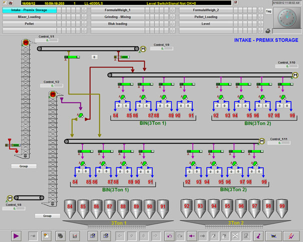
Loading system in HMI
In this project raw materialfill in binsby used conveyersand elevators.
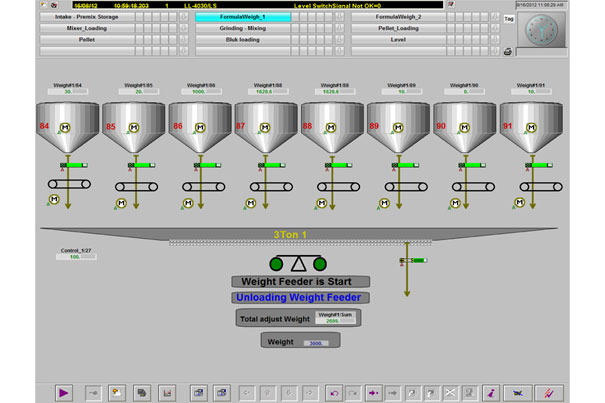
Weighting systems HMI
In this partspeed of conveyers control by PLC and Screw feeders base of recipein weighing systems, first closed all gates thenrun screwdrivers and filling raw material in weight bin after finishedloading raw material according input recipe
Raw material transmission to mill machine after milling raw materialgo to
Mixing machine after mixing oil acidin mixing machine after mixing material in Pellet mill machinecook by steam ,control of this machine isvery important because many variable must be control at the this process.
Transmissionsystems HMI